A failure in a beam may occur when it is not capable of resisting the load imposed on it. This may lead to collapse of the entire structure , so it is necessary to identify and analyze the failures in beams after their design.
Beam failures may be in flexural, torsion and shear depending on the type of the load exerted on it. There are various cause of beam failure some among them are as follows
Causes of Beam Failure
Beam failure is a term used to describe the loss of structural integrity or functionality of a beam under load. Some of the causes may be due to the material properties of the beam, such as its strength, stiffness, ductility, or toughness.
Others may be the design and construction of the beam, such as its shape, size, support conditions, or connections. Beam failure can have serious consequences for the safety and performance of structures that rely on beams to carry loads and resist forces.
The most common reasons or the causes of beam failure are
- Overloading
- Fatigue
- Corrosion
- Buckling
- Excessive bending
- Shear
- Torsion
To prevent beam failures, proper design, selection of materials, installation, and maintenance are essential. Regular inspection and monitoring can help detect early signs of damage or weakness in beams, allowing for timely repairs or replacements.
Types of Beam Failure
The mode of failures in RCC beams are majorly categorised into two types
- Flexural failure
- Shear failure

Flexural failure
Flexural strength is defined as the stress occurred just before the material starts yielding in a flexural test. It is the maximum load before the material reaches the moment of rupture.
The failure at which the load imposed on the structural member exceeds its flexural capacity is called flexural failure.
This happens when the bending moment in the beam exceeds the flexural strength of the material.
The beam cracks and breaks along the plane of maximum bending stress, usually at the bottom or top of the mid span of the beam.
Flexural failures are of three types
- Flexural tension failure
- Flexural compression failure
- Balanced failure
Flexural tension failure
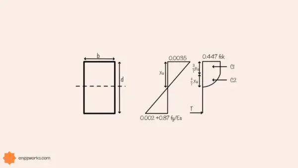
This failure is also called ductile flexural failure in which failure occurs with the yielding of the reinforcement followed by the crushing of the concrete.
This is usually observed in under reinforced sections,i.e where the reinforcement is less then the balanced section reinforcement ratio .
Failure is observed in the form of cracks developed at the tension side then extended to the compression side. The cracks so formed are vertical in orientation and lie perpendicular to most tensile fibre of the beam.
This type of failure can be avoided by proper design of the beam using IS CODE 456-2000.
Flexural compression failure
This type of failure is also called brittle failure, in which the concrete crushes before the reinforcement starts yielding.
This is usually observed in over reinforced beam sections. This failure occurs very suddenly without any prior warning in the form of deflection.
Failure can be avoided by designing under reinforced section rather than over reinforced section and also by providing reinforcement in the compression side to increase its compression strength.

Balanced failure
The failure in which the concrete crushes and the steel yields at the same time is called balanced failure.
Shear failure
The inability of the beam to resist the shear force caused by the applied loads on the member results in shear failure. Shear force acts along a plane parallel to the direction of force and hence, producing a sliding failure on beam.
This failure usually occurs suddenly without warning, and can result in a diagonal crack on the beam, but it can be easily determined by checking out the excessive deflection or development of cracks, which gives an advance warning about the probable occurrence of shear failure.
Shear failure is further classified into 4 types
- Diagonal tension failure
- Shear compression failure
- Splitting shear failure(true shear failure)
- Anchorage failure
Diagonal tension failure
This failure initiates with vertical or flexural cracks at the tension zone (bottom) of the beam due to flexural tensile stresses. Now with further increase in the load on the beam crack strengths and grow along the length and width extending towards the point of application of load showing a little diagonal deflection.
To avoid such failure web reinforcement should be provided and the ratio of shear span to depth taken as greater than 2.

Shear compression failure
Failure occurs with the development of cracks in the compression zone of the beam cross- section and finally failure occurs where the compressive strength of concrete is exceeded
Shear compressive failure results in crushing of concrete at the tip of the diagonal crack around the point of application of load .

Splitting shear failure(true shear failure)
When the shear span to depth ratio is less than one this type of failure is commonly seen. This type of beam is called deep beam in which the loads are directly transferred to supports and shear strength is much higher than the ordinary flexural beam.

Anchorage failure
This type of failure is the splitting of concrete along the longitudinal reinforcement (before compression failure can occur) due to small diagonal cracks. It occurs when the main reinforcement is not adequately anchored beyond the crack.


