The shear modulus of steel, denoted G, is a fundamental mechanical property dictating the elastic shear behavior of solid materials like structural steel.
As opposed to Young’s modulus which measures resistance to normal strains, the shear modulus of steel quantifies stiffness under pure transverse shearing loads.
An accurate value is essential for modeling the precise load-deformation response and calculating shear stresses and strains in steel components such as beams, shafts, and connections.
However, properties like composition, heat treatment, temperature, crystal structure, and material orientation can all influence the shear modulus of steels considerably.
This variability means assuming a single G value for all steel analysis leads to erroneous predictions of shear and flexural stiffness and underestimates deflections.
Through compiled test data, advanced models, and understanding processing influences, engineers can incorporate accurate, tailored shear modulus of steel for specific alloys that reflect measurable material behavior – rather than resort to basic simplifications. This enables realistic structural simulations.
Structural engineering design fundamentally depends on the accurate material properties of steel.
While extensive research quantifies the Young’s modulus and yield strength, comparatively far less emphasis gets placed on determining shear modulus of steel.
However, this elastic constant directly impacts predictions of beam deflection, torsional deformation, buckling loads, and fatigue life.
Shear moduli hold increased importance for high strength alloys optimized for weight savings in design.
Unfortunately, generalized assumptions rarely hold even for basic carbon steels given the sensitivity to composition, heat treatment, microstructure, temperature, and testing direction.
Calculating the Shear Modulus of Steel
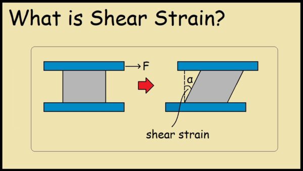
Shear modulus of steel G quantifies the elastic response under shear strain.
For structural analysis, an accurate value is required for modeling beam deflection and torsional stiffness.

Using principles of elasticity theory, the shear modulus for isotropic steel can be calculated as:
G = E / (2(1 + ν))
Where E = Young’s modulus, and ν = Poisson’s ratio.
Typical values for structural carbon steels are E = 200 GPa and ν = 0.3, giving G = 80 GPa.
However alloying additions can cause significant variation.
Derivation of the General Shear Modulus of steel .
The formula for shear modulus of steel can be derived from fundamental stress-strain relationships and the elastic potential energy equation.
Applying pure shear stress gives the proportionality:
τ = Gγ
Where γ is engineering shear strain.
The modulus G quantifies the resistance to shear deformation.
Rigorous derivation involves coordinate transformations, substitution into Hooke’s Law and mathematical manipulations.
Tabulated Values of Shear Modulus for Steel Alloys
The composition and heat treatment of steel creates wide variance in G.
Typical ranges are:
- Plain carbon steels: 70 – 85 GPa
- High strength alloy steels: 75 – 110 GPa
- Stainless steel grades: 70 – 190 GPa
Given this sensitivity, published tabulations of experimentally measured values categorized by alloy provide reliable data for analysis instead of estimations.
Effect of Heat Treatment on the Shear Modulus of Steel
While steel’s Young’s modulus is considered relatively invariant to thermal processing, shear modulus can reduced up to 15% from cold worked states when annealing, normalizing or quenching.
This stems from the modulus’s dependence on crystal structure and dislocation density. Accounting for processing effects provides accurate stiffnesses.
Dependence of Shear Modulus on Microstructure of Steel
At the atomic scale, the shear modulus of iron crystals varies by orientation, ranging from 47 GPa to 121 GPa across body centered cubic ferrite and face centered austenite phases.
Introducing alloying particles that impede dislocation motion also increases the modulus.
This microstructural sensitivity produces anisotropy.
Nonlinear Shear Modulus During Steel Plastic Deformation
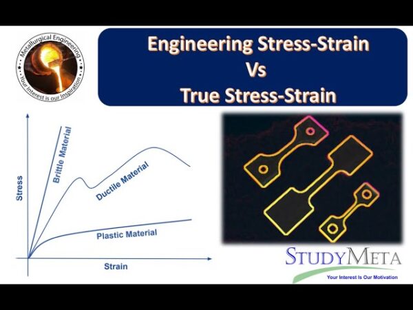
Once yielding occurs under increasing load, measurements reveal the shear modulus reduces exponentially with greater plastic strain.
This nonlinear drop can be integrated into advanced numerical models to simulate the macro-scale onset of ductility and compliance as a function of shear stress history.
Shear Modulus Test Method Standards for Steel (EN 10002)
The preferred test for determining shear modulus of steel is through non-destructive pulse echo ultrasound measurements due to the method’s accuracy and repeatability in a lab setting.
The moduli can also be backed out of tensile tests using a Poisson’s ratio assumption.
Standards group these techniques together for consistent results.
Temperature Dependence of Shear Modulus in Mild Steel
The shear modulus varies according to temperature sensitivity relations of the form:
G = Go [1 + β(ΔT)]
Where Go is the baseline shear modulus and β captures the thermal modulus coefficient.
For mild steel, β = -5×10⁻⁴ making G 80GPa at room temperature and 75GPa at 400°C, a 6% decline.
Anisotropic Shear Modulus in Rolled Steel Plate
Rolling steel ingots into plate stock induces grain flow contours and texture which reduces symmetry.
This causes orthotropic behavior where the shear modulus varies directionally from 80 GPa parallel to rolling compared to 84 GPa transverse.
Engineers account for this anisotropy in advanced analysis.
Modeling Steel Materials with Shear Modulus Inputs
Specialty finite element solvers like ABAQUS enable defining temperature and direction dependent shear moduli for steel alloys.
Applying true material properties predicts performance more accurately than simpler linear approximations, especially under cyclic loading.
The advanced software leverages test data.
In summary, precisely determining steel’s shear modulus forms a critical link between true material behavior and structural simulations. It enables realistic predictions of deformations essential for proper design.
With strong understanding of experimentally measured moduli, tabulated databases, processing and microstructure effects, and advanced modeling techniques, engineers can move beyond simple assumptions toward solutions reflecting the real steel modulus.


