Bending stress refers to the stress induced in a beam or structural member when external forces or moments are applied perpendicular to the longitudinal axis, causing bending.
It arises when one part of a material is in tension while the other is in compression.
The larger the bending moment and the longer the beam, the larger it will be.
Beams and bars in buildings, bridges, machines and other load bearing structures often experience bending stresses from vertical loads that induce bending moments.
Understanding this stress is key for determining the adequate strength and stiffness of these structural components during design.
The maximum stress dictates the cross section dimensions and material strength required for safe functionality over the structure’s lifetime.
Simple beam theory can be used to model beams under bending loads and calculate parameters like maximum bending moment, curvature, beam deflection, shear force, and reactions at supports.
Formulas for normal stress, shear stress and strain can then determine if a beam’s strength and rigidity are sufficient.
Controlling deflections and cracking are other reasons engineers analyze it.
With an increasing applied moment, the beam ultimately fails by excessive bending.
Proper engineering design limits stresses to safe margins well below this failure point.
Bending stress constitutes a primary design consideration for beams and components subjected to flexure loads.
Standard Formula for Calculating Bending Stress in Beams
The fundamental stress equation used extensively across beam analysis and design equals:
σ = Mc/I
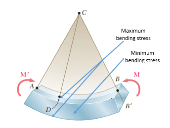
Where σ = bending stress (Pa, psi), M = bending moment (Nmm, in-lbs), c = distance from neutral axis (mm, in), I = second moment of area or moment of inertia (mm4, in4).
Bending Stress Distributions in Wide Flange Beam Sections
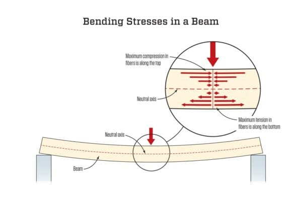
stress patterns along beam cross section depth follow a linear distribution – maximum tension on lower extreme fibers and maximum compression on upper extreme fibers.
Stress concentrates on the flange edges in wide flange I-beams rather than the web center.
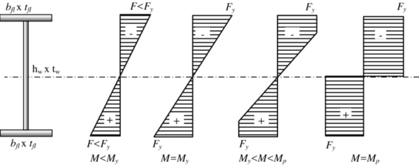
Contrasting Bending Against Shearing Stresses
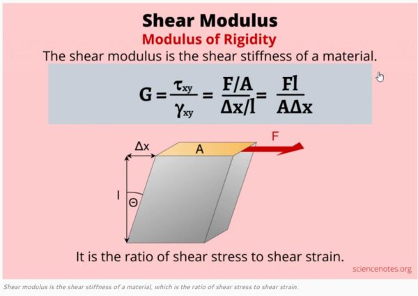
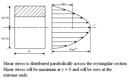
Shearing stresses act perpendicular to a member’s axis within a plane while bending align along the beam length axis.
Shear stresses vary across the cross section but prove zero on surface points where bending maximize.
Role of Second Moment of Area in Resisting Bending
A cross section’s second moment of area or moment of inertia (I) about its neutral plane axis signifies its bending stiffness and resistance.
Higher I mean lower bending stress for a given applied moment, enabling optimized beam shape efficiency.
Assumptions and Limits of Theory
Classical bending theory assumes linear elasticity and small deflections with pure bending. It breaks down for dynamic loads inducing inelastic material behavior or buckling from compressive stresses.
Modern computations overcome simplifications.
Example Problems Calculating Stress Magnitude
By inputting measured loads, member dimensions, modulus of elasticity values etc. into bending equations, engineers determine stress margins staying within acceptable material strength limits for design conformity.
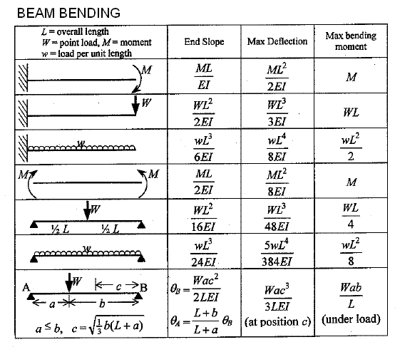
Reinforcing Techniques to Reduce High Stresses
Approaches for addressing overstressed members from excessive bending moments include reshaping components into optimal orientations, specifying higher strength materials, using reinforcement ribs, or integrating composite wraps.
Elevated Stresses Near Discontinuities and Holes
Stress concentration factors magnify localized bending stresses around sudden cross section changes.
Generous fillet radii and gusseted support plates mitigate concentration issues from holes under bending.
Instrumentation Innovations For Dynamic Bending Data
Electrical resistance strain gage rosettes with calibrated shunt resistors produce accurate dynamic bending stress measurements for fatigue analysis without signal conditioning demands, enabling wireless sensor networks.
FAQ- bending Stress
1. How is bending stress calculated?
The maximum bending stress can be calculated using the flexure formula: σ = Mc/I Where: σ = Maximum Bending Stress M = Internal Bending Moment c = Distance from Neutral Axis to Outer Fibers I = Second Moment of Area
2. At what point is bending stress the highest?
The maximum bending stress occurs at the outermost fibers of the beam, furthest away from the neutral axis. The top and bottom surfaces of a beam experience the largest tension or compression.
3. What is the difference between bending stress and normal stress?

Bending stress is a more specific type of normal stress. When a beam experiences load like that shown in figure one the top fibers of the beam undergo a normal compressive stress. The stress at the horizontal plane of the neutral is zero. The bottom fibers of the beam undergo a normal tensile stress.
Advanced FEA Simulating Real-World Bending Scenarios
Sophisticated finite element analysis readily handles intricate parameters from plate and shell combinations under compound loading for determining realistic stress distributions in complex structures.
Accurately evaluating stresses ensures structural design integrity against excessive deformations or failure from applied moments.
Both analysis fundamentals combined with modern simulations provide the vital insights for infrastructure longevity.


