Engineers must understand and accurately determine the stresses in cantilever beam designs to create safe, optimized structures.
Cantilever beams experience various stresses including bending stress, shear stress, and deflection stress.
Carefully analyzing these stresses using calculations, formulas, and analysis techniques allows the maximum load capacity to be determined.
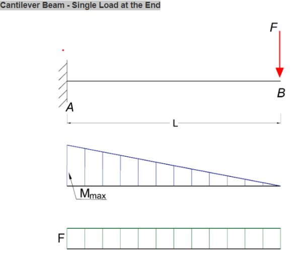
Calculating Stress in Cantilever Beams with point load
point loads are common for cantilever structures such as balconies and signs.
stress in Cantilever Beam Formulas – The primary formula for calculating stress in a cantilever beam is:

Maximum Reaction Force
at the fixed end can be expressed as:
RA = F (1a)
where
RA = reaction force in A (N, lb)
F = single acting force in B (N, lb)
Maximum Moment
at the fixed end can be expressed as
Mmax = MA
= – F L (1b)
where
MA = maximum moment in A (Nm, Nmm, lb in)
L = length of beam (m, mm, in)
This is the fundamental flexural stress formula used to determine the bending stress from applied loads at any point on a cantilever beam based on beam geometry and material properties.
This formula assumes an elastic, linearly elastic isotropic material. Stresses may exceed yield strength and the beam may experience some plastic deformation.
Some key notes when using this equation:
- It gives stress due to BENDING ONLY, not including shear stress or deflection stress.
- Parameters must be consistent (N vs lb, m vs in)
So in summary, the foundation of cantilever beam stress analysis is this flexural stress formula from applied loads.
Cantilever Beam Stress Calculations
By using the cantilever beam stress formulas, calculations can be performed to find stresses at any point. Key calculations include determining…
Stress
The stress in a bending beam can be expressed as
σ = y M / I (1d)
where
σ = stress (Pa (N/m2), N/mm2, psi)
y = distance to point from neutral axis (m, mm, in)
M = bending moment (Nm, lb in)
I = moment of Inertia (m4, mm4, in4)
Deflection Stress Factors
In additional to tensile and compressive stresses, deflection stress plays a key role in cantilever design. Deflection stress is calculated by…
Maximum Deflection
at the end of the cantilever beam can be expressed as
δB = F L3 / (3 E I) (1c)
where
δB = maximum deflection in B (m, mm, in)
E = elastic modulus (N/m2 (Pa), N/mm2, lb/in2 (psi))
I = moment of inertia (m4, mm4, in4)
b = length between B and C (m, mm, in)
Maximum Stress in Cantilever Beams
Maximum stresses establish the load capacity limits for cantilever beams. For safe design, the maximum stresses should not exceed…
The maximum moment in a cantilever beam is at the fixed point and the maximum stress can be calculated by combining 1b and 1d to
σmax = ymax F L / I
Stresses in Cantilever Beams with UDL
Cantilever beams often support uniformly distributed loads (UDL) in structural design cases. The stresses in a cantilever with UDL…

Maximum Reaction
at the fixed end can be expressed as:
RA = q L (3a)
where
RA = reaction force in A (N, lb)
q = uniform distributed load (N/m, N/mm, lb/in)
L = length of cantilever beam (m, mm, in)
Maximum Moment
at the fixed end can be expressed as
MA = – q L2 / 2
Maximum Deflection
at the end can be expressed as
δB = q L4 / (8 E I)
where
δB = maximum deflection in B (m, mm, in)
q – Uniform load (N/m, N/mm, lb/in)
L – Length of beam (m, mm, in)
I – Moment of Inertia (m4, mm4, in4)
E – Modulus of Elasticity (Pa, N/mm2, psi)
y – Distance from neutral axis (m, mm, in)
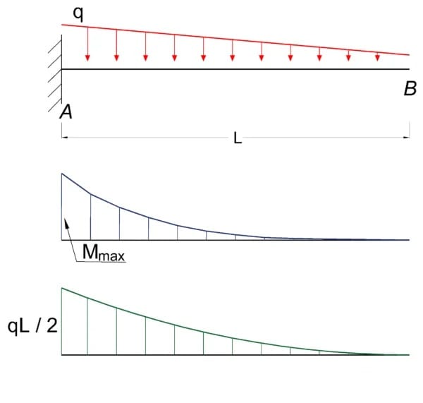
Cantilever Beam – Declining Distributed Load

Maximum Reaction Force
at the fixed end can be expressed as:
RA = q L / 2 (4a)
where
RA = reaction force in A (N, lb)
q = declining distributed load – max value at A – zero at B (N/m, lb/ft)
Maximum Moment
at the fixed end can be expressed as
Mmax = MA
= – q L2 / 6
where
MA = maximum moment in A (N.m, N.mm, lb.in)
L = length of beam (m, mm, in)
Maximum Deflection
at the end of the cantilever beam can be expressed as
δB = q L4 / (30 E I)
where
δB = maximum deflection in B (m, mm, in)
E = modulus of elasticity N/m2 (Pa), N/mm2, lb/in2 (psi))
I = moment of inertia (m4, mm4, in4)
Conclusion
Properly determining and analyzing the stresses in cantilever beams provides the necessary insight into beam capacities and failure modes.
By following the best practices highlighted, civil engineers can efficiently design safe, optimal cantilever beams for infrastructure and construction projects.
The key considerations include accurately calculating stresses using the correct formulas, analyzing deflection and stress distribution, checking for maximum allowable stresses, and performing analysis for combined or concentrated point loading scenarios.
This comprehensive stress analysis ensures cantilever beam designs minimize cost and safety risk.


