Stress calculations for Beams constitutes a central aspect within structural design across civil engineering.
By computing induced stresses, engineers confirm beam components withstand applied loads without failure.
Among principle stresses induced in beams under bending loads, designing for maximum normal stresses on extreme fibers proves most critical.
However, properly determining shear stresses also proves necessary to assess shear cracking and reinforce accordingly.
While simple beam configurations facilitate analytical solutions, complex modern structures require numerical methods and software to simulate real-world behavior.
Beams undergo complex loading scenarios inducing bending, shear, torsional and axial stresses.
Designers primarily assess bending stresses on extreme fibers and shear stresses causing cracking.
Accurately calculating stress distributions proves necessary for appropriate structural sizing and reinforcement.
Advanced analysis has progressed from manual computations using singular beam assumptions to refined finite element analysis.
Yet core concepts around basic stress equations and allowable capacities per codified design procedures remains relevant.
Gaining comprehensive insights on stress calculations for beams equips engineers to optimize structural performance.
As analysis capabilities progress, the fundamentals around stress computations continue providing the roadmap for developing safer, more efficient beam designs.
Shear Stress Calculations for Beams of timber and wood
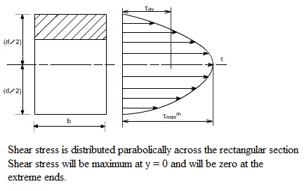
For horizontally laid rectangular wood beams under bending loads, the shear stress formula equals:
τ = (1.5P) / (bd2)
Where P is the vertical load, b is the beam width, and d equals beam depth. Comparison against wood shear strength ratings determines ample safety.
Analyzing Stress Distribution in Wide Flange I-Beams
Bending stress distributions in I-beams’ flanges follow a linear path of normal stresses reaching maximum tension/compression at top/bottom fibers.
Loading direction and beam fixity impacts gradients. Refined analysis via finite element modeling reveals more complex stress concentration patterns around web-flange junctions.

Computer-Based Stress Simulation of Reinforced Concrete Beams
Modern structural analysis software expedites stress calculations for beams made of complex reinforced concrete with iterative design methods and mechanisms like equivalent loads for reducing composite cross-sections into a single beam for batch computations.
Powerful Finite Element Analysis accurately captures nonlinear concrete cracking and steel yielding effects.
Maximum Bending Stress and Deflection of Simply Supported Beams
Applying singular beam theory, the max bending stress formula for simple span beams with central point loads simplifies to:
σmax = (PL)/(4bd2)
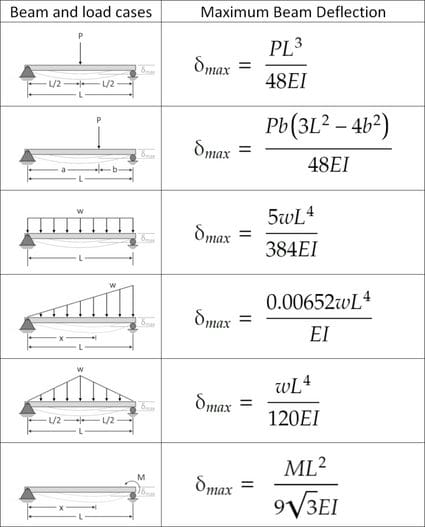
Whereas max deflection using the moment area method becomes:
δmax = (5PL3) / (384EI)
E is elastic modulus and I equals second moment of inertia.

How Stress Concentration Impacts I-Beam Strength
Discontinuities like sudden changes in cross-section, holes or loading/support points amplify localized stresses.
Through notch sensitivity factors and fracture mechanics, designers prevent fatigue failures or plastic collapse from stress concentrations in critical I-beam applications.
Manual Calculation Examples for Beam Deflection and Normal Stress
Using singularity functions and superposition concepts, student engineers combine solutions for simpler load cases into final beam deformation and stress fields.
This facilitates hand verification of analysis software outputs.
Comparing Analytical and FEA Solutions for Beam Bending Stresses
Validated finite element models provide more accurate bending stress solutions by capturing real discontinuities, nonlinear material behavior, and complex loading scenarios often idealized through classical beam assumptions.
The multiple iterative computations surpass manual solution practicality.
Overview of Allowable Stress Design Techniques
Allowable stress calculations for beams require areas or section moduli with bending and shear stress equations using reduced capacities per safety factors codified from beam material testing.
This method ensures member soundness under specified dead, live, wind etc. load combinations.
With computing tools ranging from basic mechanics to advanced FEA at their disposal alongside codified design procedures, civil engineers continue innovating beam-intensive structures, from soaring skyscrapers to expansive bridges, that withstand the test of time.
FAQ – Stress Calculations in Beams
What is a normal stress in a beam?
A normal stress is a stress that occurs when a member is loaded by an axial force. The value of the normal force for any prismatic section is simply the force divided by the cross sectional area. A normal stress will occur when a member is placed in tension or compression
What are the different stresses induced in beams?
The main stresses induced in beams are:
Bending stress – Developed due to bending action of beam caused by external loads
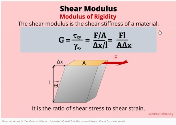
Shear stress – Result of shear forces acting perpendicular to beam axis
Axial stress – Caused by axial tension or compression loads
What parameters do one need for stress calculations for beams?
Key parameters needed are:
Load magnitude and configuration
Beam geometry – Cross sectional dimensions, shape, length
Support conditions – Fixed, simply supported, overhanging, etc
Material properties – Strength, stiffness
Stress Determination Guidelines per AISC Steel Construction Codes
AISC specifications codify standard procedures for computing stresses in steel beams from axial, bending, torsional actions along expected P-M, P-M-V interaction values.
This facilitates design optimization balanced against stability risks from elastic/inelastic buckling modes.
Accurately determining beam stresses forms the cornerstone of structural integrity and safety.


