The Young’s modulus of aluminum is a crucial material property that defines its ability to resist deformation under stress—a fundamental concept for engineers, designers, and researchers across sectors ranging from aerospace to construction.
Whether selecting materials for lightweight structures or optimizing manufacturing parameters for aluminum alloys, understanding the aluminum Young’s modulus and its variations is essential for performance, safety, and innovation.
As an intensive property independent of geometry, aluminum’s Young’s modulus ranges from 65 to 75 GPa, around a third that of carbon steel.
This lower modulus indicates greater elastic deformability under load, affecting engineering considerations around deflection control and stiffness.
This article will provide a technical deep dive into the Young’s modulus of aluminum.
What Is Young’s Modulus of Aluminum?
Young’s modulus, sometimes called the modulus of elasticity, quantifies a material’s stiffness or resistance to elastic deformation when subjected to load.
For aluminum, this property is especially notable due to its excellent ratio of strength to weight, making it a favorite for modern engineering applications.
Young’s modulus for the purest form of aluminum is typically around 69 GPa (gigapascals), though values from 68 to 71 GPa are commonly reported depending on specific purity, processing, and measurement conditions.
Subsequently, what is aluminum’s Young’s modulus?
It’s the material’s measure of elasticity under linear loading, with higher values indicating a stiffer material.
Why Young’s Modulus Aluminum Matters
- Design: Engineers use aluminum’s Young’s modulus to calculate deformations, limits, and required cross-sections for beams, plates, and other structural elements.
- Comparison: The Young’s modulus aluminum imparts to a product is contrasted with other metals: steel’s modulus (~200 GPa) is much higher, while magnesium (~45 GPa) and titanium (~110 GPa) present alternatives for lighter applications.
- Innovation: Advanced alloys and new composite materials often aim to balance high aluminum Young’s modulus with reduced weight or improved corrosion resistance.
Young’s Modulus Aluminum Types and Alloys
Aluminum isn’t usually used in its pure form; aluminum alloys are tailored to specific mechanical and chemical requirements. Young’s modulus of aluminum alloy varies with alloying elements (magnesium, silicon, copper, zinc, etc.), but most domestic and industrial aluminum alloys cluster around 68–72 GPa:
- 6061 Aluminum Alloy: Young’s modulus for aluminum alloys like 6061 is about 68.9 GPa, making it suitable for structural components.
- 7075 Aluminum Alloy: Slightly stiffer, 7075 features a Young’s modulus of 71.7 GPa for aluminum.
Young’s modulus of aluminum alloys rarely exceeds 75 GPa or falls below 65 GPa at room temperature unless radically modified.
Young’s Modulus of Aluminum vs Temperature
The aluminum alloy Young’s modulus vs. temperature relationship is important for high-tech and harsh-environment applications. As temperature rises, modulus decreases subtly but consistently:
- At room temperature, Young’s modulus for aluminum plates, beams, and extrusions is about 69 GPa.
- Above 150°C, a drop towards 65 GPa or lower may be observed for some alloys, especially in thin sections. Modulus reduction is almost always reversible if the temperature cycles without structural damage.
- Aluminum alloys subjected to persistent high temperatures may experience additional effects like creep, but what happens to modulus after material has yielded but not failed? For aluminum, the Young’s modulus of Al remains essentially unchanged until plastic deformation sets in; then, the post-yield modulus (tangent modulus) is much reduced, often to 2–5 GPa or less.
Module Young Aluminum: Practical Applications
Understanding the elasticity modulus of aluminum is essential for providing critical guidance in the following areas:
- Structural Analysis: Calculating deflection in aluminum beams (e.g., aluminum beam Young’s modulus) for bridges, buildings, and frames.
- Aerospace: Lightweight panels, where Young’s modulus for aluminum plates ensures stability with minimal mass.
- Automotive: Crash resistance and flexibility in body panels—modulus guides design tolerances.
- Electronics: Precise tolerances for heatsinks and chassis depend on the typical Young’s modulus of aluminum (generally cited as 69 GPa).
Young’s Modulus of Aluminum in Data Tables
Here’s a comparison table for quick reference to Young’s modulus for aluminum in GPa and other types:
| Aluminum Type | Young’s Modulus (GPa) | Notes |
|---|---|---|
| Pure Aluminum | 69 | Most common reference value |
| 6061 Alloy | 68.9 | Widely used for structures |
| 7075 Alloy | 71.7 | Aerospace grade, higher strength |
| Room Temperature Aluminum | 69 | Uniform for most alloys |
| Heated to 200°C | 65–66 | Minor reduction, temporary unless alloy affects |
| Post-yield (Plastic Region) | 2–5 | Only after permanent deformation |
Module Young Aluminium: Measurement and Units
Young’s modulus (E) for aluminum is commonly measured in:
- The standard for scientific and engineering use is GPa (Gigapascals).
- psi (pounds per square inch) in some regions:10,000,000 psi 10,000,000 psi is equivalent to 69 GPa.
Factors Affecting Young’s Modulus for Aluminum
- Alloying Elements: Additions like copper, magnesium, and zinc can alter the stiffness by a few percent and affect aluminum alloys’ Young’s modulus.
- Work Hardening and Heat Treatment: Can slightly modify the modulus, but the effect is usually less pronounced than the impact on yield strength or ductility.
- Impurities and Inclusions: In commercial alloys, inclusions rarely reduce modulus unless heavily concentrated.
Young’s Modulus Aluminum Implications in Design
- Flexural Rigidity: Aluminum’s moderate modulus supports flexible yet strong structures, ideal for both static and dynamic loads.
- Vibration Damping: More elastic than steel, aluminum allows for better vibration absorption in machinery.
- Failure Analysis: Once aluminum yields, its modulus drops sharply—what happens after the material yields but does not fail is a low tangent modulus; structures should be designed to avoid reaching this regime unless energy absorption is desirable.
Young’s modulus of Al: Advanced Topics
- Alumide YOung’s Modulus: New composite materials such as alumide (a blend of aluminum and polyamide) can have a modulus dramatically lower than that of pure metals, which is useful for 3D printing and prototyping applications.
- Module de Young Aluminium: French-language references use similar data (module de Young aluminium ~69 GPa).
- The terms “Young’s modulus of Al” and “Al’s Young’s modulus” refer to the same nominal range, despite their varied spellings.
Environmental Effects on Young’s Modulus of Aluminum
- Corrosion: Superficial oxidation does not significantly alter Young’s modulus for aluminum.
- Temperature cycling yields minor, reversible changes, except in extreme alloys or with prolonged exposure.
- Surface Treatments: Anodizing or painting does not affect the core modulus of aluminum, only its surface properties.
Young’s Modulus for Aluminum Plates and Beams
Engineers routinely compute elastic deflection and stability using Young’s modulus values for both aluminum plates and aluminum beams. For standard sections, these values are reliable:
- Plates: 69±2 GPa69 \pm 2 \, \text{GPa}69±2GPa
- Beams: 69±2 GPa69 \pm 2 \, \text{GPa}69±2GPa
This allows precise modeling for bridges, trusses, and frameworks.
Typical Young’s Modulus of Aluminum
TThe most commonly cited Young’s modulus of aluminum in literature, engineering handbooks, and databases ranges from 68 to 72 GPa, which provides designers with predictable values for their calculations.
What Is Aluminum’s Young’s Modulus? (FAQ)
What is aluminum’s Young’s modulus?
It’s the modulus of elasticity, describing resistance to elastic deformation, nominally 69 GPa for room temperature pure and alloyed aluminum.
What is Young’s modulus E for aluminum plates?
Young’s modulus for aluminum plates is consistently 69 GPa, and the thickness and alloy composition have minimal impact unless they are significantly altered.
Young’s Modulus in Modern Materials Science
WAs demand grows in robotics, aerospace, and transport, the Young’s modulus of aluminum and its alloys becomes a key parameter in modeling efficiency. The Young’s modulus of elasticity of aluminum underpins predictive algorithms in AI-driven design platforms, deep-learning models for digital twins, and generative engineering solutions for next-gen smart infrastructure.
Summary Table: Young’s Modulus for Aluminum Types
| Application | Young’s Modulus (GPa) | Comments |
|---|---|---|
| Aerospace Sheet | 70 | High stiffness/alloyed |
| Automotive Panels | 69 | Balanced for flexibility |
| Bridge Beams | 69 | Uniform modulus |
| Marine Frames | 68.8 | Resistant to corrosion |
| Consumer Electronics Chassis | 69 | Lightweight/durable |
| 3D Printed Alumide | 4–10 | Much lower than metallic |
Effect of Heat Treatment on Young’s Modulus of aluminum
Heat treatment modifies the microstructure of aluminum alloys, which directly impacts mechanical properties such as Young’s modulus.
Solubilization followed by aging generally increases the elastic modulus through precipitation hardening mechanisms.
Reported elastic modulus values for 6061 aluminum can increase by up to 14% when the material is age-hardened compared to its solution-treated state.
Why is the Young’s modulus of aluminum lower than that of steel?
Aluminum has a face-centered cubic lattice at the atomic level, allowing more slip plane deformation than steel’s body-centered structure.
Deformation along slip planes results in lower resistance to uniaxial loading, leading to lower elastic modulus values for aluminum (approximately 68-70 GPa) compared to steel (approximately 200 GPa).

Highest Young’s Modulus of aluminum alloys Values
Although lower than steel, premium aerospace-grade aluminum alloys like 2024, 7075, and 6061 can reach Young’s modulus values of 73–75 GPa in peak-aged tempers thanks to alloying additions like Cu and Mg.
Particle-reinforced composites with SiC or Al₂O₃ have reported modulus values approaching 100 GPa as reinforcement hinders lattice distortion.
Relationship Between Young’s Modulus and Aluminum Strength
While strength depends on impeding dislocation motion, Young’s modulus is determined solely by the atomic bonding force that resists elastic lattice distortion.
However, precipitate hardening methods that impede dislocations also increase the stiffness of the lattice, resulting in an indirect correlation between the higher strength of aluminum alloys and their modulus values.
How to Calculate Young’s Modulus for Aluminum Plate
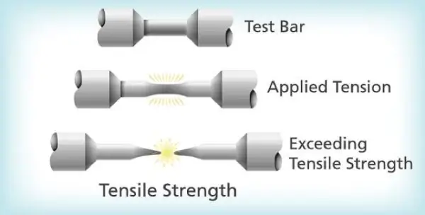
Young’s modulus is calculated by dividing tensile (or compressive) stress by the axial strain in the elastic deformation region before yielding.
Depending on the alloy and temper, the resulting Young’s modulus values can range from 65 to 75 GPa.
Young’s Modulus – Aluminum 6061-T6 Temper
The T6 heat treatment temper involves solution heat treating followed by artificial aging to achieve peak strength, which maximizes the elastic modulus compared to lower temperature tempers like T4, due to the effects of precipitation hardening.
Aluminum Young’s Modulus vs. Temperature Graph
Young’s modulus decreases nearly linearly as temperature increases, as elevated temperatures excite increased atomic vibration, reducing bonding force and lattice resistance.
Aluminum experiences approximately a 4% reduction in Young’s modulus when the temperature increases from room temperature to 250°C.

Cold-Worked Aluminum Improved Young’s Modulus
Plastically deforming aluminum via cold working strains the lattice beyond yield, causing lattice defects and DISTORTIONS that hinder dislocation motion, restricting elastic deformation and Up to 7% higher modulus values are reported for heavily cold-rolled 5xxx and 6xxx aluminum alloys.
Young’s Modulus Aluminum Alloy Test Method Standards
ASTM E111 using strain gauges or extensometers is the standard test method for dynamically determining. Alternatively, the modulus can also be characterized by ISO 6892-1 (tensile test), ASTM C747 (ultrasonic), or ASTM E1875 (resonant frequency and damping).
Impact of Strain Rate on Aluminum Young’s Modulus Measurement
Aluminum exhibits slight modulus dependence on strain rate—the reported shear modulus under ultrasonic frequencies (~104 Hz) is around 5% higher than quasistatic.
The viscoelastic behavior of aluminum requires that the test strain rate be matched to the end-use application profile when generating material data.
Conclusion: Young’s Modulus as a Design Cornerstone
The Young’s modulus for aluminum stands as a design cornerstone, informing calculations for everything from skyscraper frameworks to lightweight satellites.
No matter how it’s written, the Young’s modulus of aluminum is always 69 GPa in engineering books and material databases around the world.
For maximum stability and performance, always consider aluminum’s Young’s modulus, alloy type, temperature effects, and design loads.
With predictable properties and proven versatility, aluminum continues to shine as the material of choice for the world’s most innovative engineering and manufacturing solutions.


