Maximum shear stress is a critical concept in structural design and analysis that every civil engineer must understand.
When forces act on an object, they induce internal stresses – normal stresses, shear stresses and occasionally combined states of stress.
Shear stress refers to stresses induced perpendicular to an applied load causing adjacent parts of a material to slide relative to each other.
As shear stresses increase on any section of a structural member, at some point, the maximum shear stress capacity of the material will be reached, resulting in shear failure and rupture.
Determining the maximum shear stress that a material can withstand is vital for properly sizing structural members like beams, columns, shafts, pressure vessels etc.
Maximum Shear Stress – Introduction
Analyzing maximum shear enables engineers to design components that are safe against shear failures.
Maximum shear is vital concept in analysis of civil engineering components like beams, columns, mechanical parts and more.
Calculating and accounting for maximum shear allows safe design by avoiding shear failure.
Calculating Values for Maximum Shear
The maximum shear in a structural member refers to the maximum intensity of shear force per unit area that a material can safely withstand before mechanical failure.
The maximum shear formula helps determine this allowable capacity:
Max Shear Stress = VQ/It

Where:
V = Applied shear force
Q = First moment of the area above or below neutral axis
I = Moment of inertia of cross section
t = Thickness at the location where shear stress acts
Understanding how to accurately calculate maximum shear stress enables structural designers to size members appropriately.
Overview of Maximum Shear Definition
Simply put, maximum shear stress is the maximum amount of shear load a material can handle per unit area before failure.
This helps define the mechanical strength capabilities against transverse internal forces.
Analysis involves comparing maximum induced shear stress from loading against the maximum permissible shear value for the material used based on yield strength.
Examining Maximum Shear Stress in Beams
In beam analysis and design, max shear stress often governs sizing of transverse reinforcement and capacity. Some key beam calculations related to maximum shear include:
- Calculating shear force diagrams
- Determining the location of max shear in a beam from diagrams
- Sizing stirrups and shear reinforcement
- Verifying shear capacity especially near supports
Beams fail when induced shear exceeds the max shear strength along vulnerable sections, so analyzing shear stress is vital.
Maximum Shear Stress in Pipes and Vessels
In addition to beams, calculating maximum shear stress is important for pipe and pressure vessel design. Key aspects when analyzing piping and cylinders include:
- Hoop and longitudinal stresses from pressure
- Combining shear stress due to torsional effects
- Sizing wall thickness to avoid burst or rupture failure modes
Permissible shear values govern thickness requirements especially for high pressure vessels and piping systems.
Overview of Maximum Permissible Shear Stress Values
For structural design standards, maximum permissible shear stress values for different materials help define capacity. Some example values include:
- Low carbon steel: 0.3xFy (yield strength)
- Stainless steel: 0.17xFy
- Concrete: 4√f’c (compressive strength)
- Timber: varies by wood grade
These capacities prescribed by codes help engineers appropriately size members.
Maximum Shear Stress Sample Calculation
As an example, calculate the max shear stress on a W12x50 steel beam with an applied shear force of 65kips and a web thickness of 0.515 inches.
VQ = Shear Force x Section Modulus
I = Moment of Inertia = 929 in4
t = Thickness = 0.515 in
Max Shear Stress = VQ/It = (65 kips x 194 in3) / (929 in4 x 0.515 in)
Max Shear Stress = 7.2 ksi
This can be compared to the allowable value for shear failure.
Key Equations for Maximum Shear Stress Analysis
Some of the main equations used when analyzing maximum shear stress include:
- Max Shear Stress = VQ/It
- Allowable Shear Stress = 0.3xFy
- Shear Capacity = 0.6xFyAw (Fy is yield strength, Aw is shear area)
- Max Shear Force = Shear Diagrams
- Q = Moment First of Area Above or Below Neutral Axis
Using the right shear stress formulas allows validation of structural design integrity.
Major Factors That Affect Maximum Shear Stress
Some of the main parameters that influence maximum shear stress include:
- Applied Transverse Loads: Higher loads increase shear
- Material Strength: Higher yield/failure values increase capacity
- Section Thickness: Thicker webs reduce shear concentration
- Section Shape: Box and tubular sections resist torsion
- Members With Holes: Stress concentrations around openings
- Shear Reinforcement: Adds capacity with stirrups and ties
Considering factors that affect maximum shear enables appropriate design.
How Maximum Shear Differs from Shear Stress
While often confused, some key differences exist between maximum shear stress and shear stress:
- Shear Stress: Stress at any point
- Maximum Shear Stress: Highest stress that avoids failure
- Max Shear Governs Design: Size members based on peak capacity
- Shear Stress Variates Across Section: Max shear focuses on max value
So in summary, understanding how maximum shear stress impacts design compared to just shear stress distributions leads to safer structural elements.
frequently Asked Questions
1.What causes maximum shear stress failure?
When the maximum shear stress in a component or material exceeds the limiting shear strength, shear failure occurs. This leads to permanent deformation and damage along planes parallel to the applied shear stress.
2. where does maximum shear stress occur?
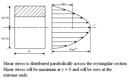
The maximum shear stress is located at the neutral axis. As the point moves further from the neutral axis, the value of the shear stress is reduced until it reaches zero at both extremes.
3. Where is maximum shear stress used or applied?
Maximum shear stress is widely used in mechanical and structural engineering disciplines for design and analysis of:
Bolts and threaded fasteners
Keys and keyways
Gears
Shafts under applied torque
Beams in bending/shear And many other applications where shear forces act to cause failure.
Conclusion and Key Takeaways
Accurately determining maximum shear stress is critical for avoiding mechanical failures in structural engineering components like beams and pressure vessels. Shear analysis validates strength and reinforcing requirements.
Key takeaways when evaluating maximum shear stress include:
- Compare max induced shear to permissible capacities
- Remember beams fail when max shear strength is exceeded
- Thicker sections and shear reinforcement help resist shear
- Consider shear stress concentrations around openings
- Use the right formulas to calculate flexure and shear
Properly accounting for maximum shear stress leads to safe and robust design.


