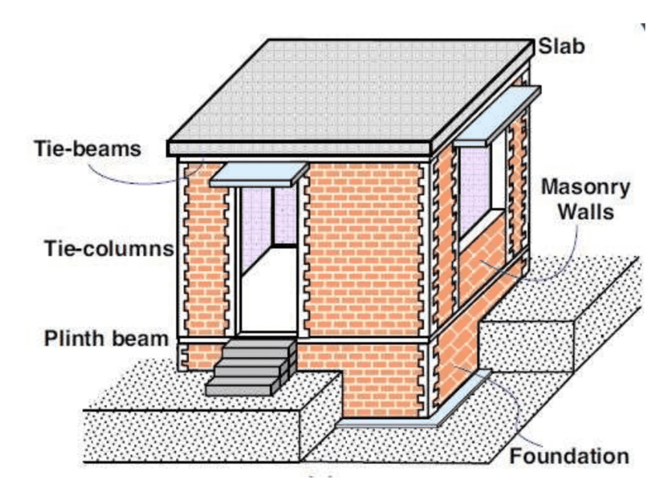
A tie beam is a critical structural member incorporated in buildings to enhance integrity and stability against lateral loads.
Tie beams strongly tie or hold together columns, walls and other vertical members on opposite sides to improve structural performance.
This comprehensive guide provides detailed insights into what tie beams are, their types, importance, design principles, reinforcements, and construction methods for multi-story buildings.
What is a Tie Beam?
A tie beam is a horizontal member spanning between columns, walls or vertical frame elements, usually at lintel level or floor/roof level. It is firmly attached to the vertical members using reinforcement dowels and stirrups.
The main purpose of tie beams is to tie the vertical members together, so that the building frame acts as an integral unit in resisting horizontal loads due to wind, earthquake or other lateral forces.
Tie beams also provide restraint against buckling failure of thin columns and walls.
Based on positioning, tie beams are classified as lintel level tie beams or roof level tie beams. Lintel level tie beams are present just above openings like doors and windows. Roof level tie beams run above the top floor level across columns/walls over the entire building plan area.
Types of Tie Beams
The different types of tie beams used in building construction are:
- Lintel level tie beam – Provided above doors, windows or openings in masonry walls.
- Roof level tie beam – Provided at roof level interconnecting columns/walls of top floor.
- Stub girder tie beam – Steel I-section stub girders connected between columns.
- Pre-cast tie beam – Tie beams manufactured offsite using modular formwork.
- Post-tensioned tie beam – High strength steel cables stressed after concreting to induce compression.
- Screed tie beam – Tie beams concealed within screed or floor finish.
Importance of Tie Beams in Construction
Some major advantages and importance of incorporating tie beams are:
- Restricts separations between vertical members due to horizontal loads
- Provides alternate load path and enhances redundancy
- Permits load sharing between weaker and stronger elements
- Improves structural integrity under seismic activity
- Minimizes potential for progressive collapse failures
- Stiffens building frames against lateral sway and drift
- Reduces differential settlements in foundations
- Helps in quick & economical construction using precast components
- Anchors non-structural elements like glass facades securely
Difference Between Tie Beam and Plinth Beam
The major differences between tie beam and plinth beam are:
Plinth beam is provided at ground level for transferring wall loads to soil. Tie beam is provided between columns to increase the stiffness of structure.
- Position – Tie beams are present at lintel or roof level, while plinth beams are at ground floor level.
- Purpose – Tie beams integrate vertical members together against lateral loads. Plinth beams transfer wall loads to foundations.
- Continuity – Tie beams are continuous over columns/walls. Plinth beams are discontinuous below walls.
- Reinforcement – Tie beams have more stirrups to resist tension. Plinth beams need only nominal stirrups.
- Size – Tie beams are deeper but narrower. Plinth beams are shallower but wider.
- Prestressing – Post-tensioning done in tie beams but not in plinth beams.
Tie Beam Design
The major considerations in structural design of tie beams are:
- Span and positioning – Based on structural layout, openings.
- Imposed loads – Self-weight, finishes, services.
- External loads – Wind, seismic, settlement-induced forces.
- Developing effective tying system using dowels and stirrups.
- Designing adequate section depth and width for stiffness.
- Reinforcement detailing – Adequate anchorage, splices, cut-offs.
- Detailing of pre-cast joints, inserts and connections if used.
- Designing post-tensioning cables and end anchorages if required.
- Limiting deflections and cracking by limiting steel stresses.
- Cutting and creating notches in tie beams to accommodate services.
Tie Beam Reinforcement
The major reinforcement used in tie beams consists of:
- Longitudinal bars – High yield strength deformed steel bars provide flexural strength.
- Vertical stirrups – 8 – 10 mm Tor steel links @ 100 – 150 mm spacing resist shear forces.
- Dowel bars – Connect tie beam to columns/walls. Pass column loads through joint.
- Cross ties – Provided in wider tie beams for effective confinement.
- Anchor bolts – Secure tie beam to foundation. Resists uplift in cantilevers.
- Prestressing tendons – High tensile steel cables stressed to induce compression.
- Cover concrete with max. 20 mm aggregate protects rebars against corrosion.
Tie Beam Details
The general details and best practices for tie beam detailing are:
- Depth ranges from 300 – 600 mm for normal buildings.
- Width is minimal, just sufficient for arrangement of main rebars.
- Longitudinal bottom reinforcement is more than tension steel for sagging.
- End anchorage is provided for bottom steel against pullout.
- Shear links are staggered near the supports against concentration of diagonal cracks.
- Sufficient embedment of dowel bars into the beam is ensured.
- Adequate cover and spacing is provided to rebars as per standards.

Tie Beam Size
The size of tie beam is determined based on the following:
- Span between columns/walls – Longer spans need deeper beams
- Imposed gravity loads on beam – Higher loads need increased depth
- Magnitude of lateral forces to be resisted – High winds or seismic forces require larger depth
- Axial forces due to post-tensioning cables – Compressive forces enhance capacity.
- Flexural and shear capacities required – Design codes specify limits
- Reinforcement percentage and arrangement – More rebars need wider sections
Typical tie beam sizes range from 230 mm x 300 mm for short 5 m spans, to 600 mm x 400 mm for longer 12 m spans.
Tie Beam Function
The major structural functions performed by tie beams are:
- Restrict horizontal separation between interconnected columns/walls due to lateral drift.
- Act as stiffening elements which enhance resistance to lateral loads.
- Permit transfer of loads from weaker to stronger structural members.
- Act as alternate load paths to limit progressive collapse.
- Contribute to overall bending and shear resistance of frame.
- Anchor and support non-structural elements like glass panels.
- In post-tensioned beams, induce beneficial compressive stresses.
- Provide restraint against out-of-plane buckling of slender columns/walls.
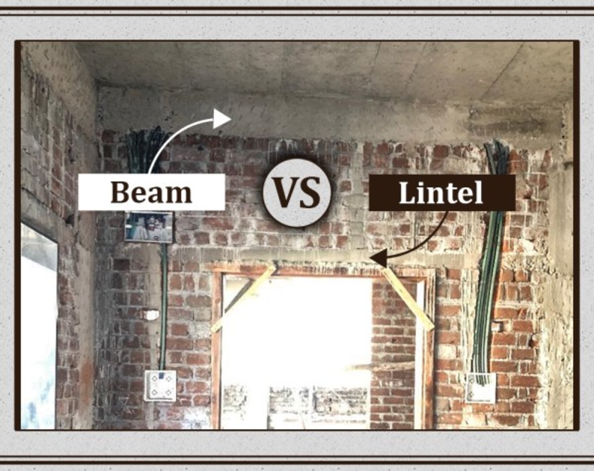
Tie Beam vs Lintel
The major differences between tie beams and lintels are:
- Lintels are narrower band elements above openings. Tie beams have much larger spans.
- Lintels support masonry courses over openings. Tie beams integrate vertical frame members.
- Lintels carry smaller imposed gravity loads only. Tie beams resist heavy gravity and lateral loads.
- Lintels have only nominal reinforcement. Tie beams have extensive reinforcement.
- Failure of lintels does not affect structural stability. But tie beam failure can be catastrophic.
- Lintels are designed as simply supported. Tie beams are effectively continuous.
Tie Beam Structural Engineering
From a structural engineering perspective, some key considerations for tie beam design are:
- Developing load path models for gravity and lateral loads.
- Analysis methods – Limit state design for strength and serviceability. Advanced FEA.
- Material design parameters – Grade of concrete and steel as per codes.
- Effective stiffness contribution of tie beams in resisting drifts.
- Non-linear effects – Progressive cracking, tension stiffening, dowel action.
- Proper reinforcement detailing for ductility and avoidance of premature failures.
- Connection design for precast beams using reinforcement couplers and dry joints.
- Design of post-tensioning – cable profile, anchorages and end blocks.
- Constructability factors – Formwork, staging, propping, transportation, lifting.
Tie Beam Calculation
Tie beam design calculations involve determining:
- Factored design loads – DL, IL, WL, EL (wind/seismic)
- Load combinations – DL + IL ± WL , DL ± EL etc. as per codes
- Effective flange widths for T-beam action
- Elastic analysis for member forces – Shear force, BM, Torsion
- Reinforcement requirement for flexure, shear
- Anchorage and splice lengths
- Deflection checks – Limits for durability
- Crack width checks – Limits for leakage & corrosion
Specialist software or spreadsheets aid complex iterative calculations. Hand methods used for preliminary sizing.
Tie Beam Construction
Key aspects in construction of tie beams are:
- Formwork and falsework design, erection and alignment
- Congestion – proper rebar spacing, assembly and lifting arrangements
- Pre-cast beam handling, transportation and erection using cranes
- In-situ concrete placement in narrow forms – need for self consolidating concrete
- Compaction – Immersion and screed vibrators
- Joint concreting if tie beam interrupted
- Water curing – ponding, wet sacking
- De-shuttering as per strength development timeline
- Prestressing – jacking equipment, anchorage control
- Grouting tendons post-tensioning
- Sequencing with column/wall construction
Tie Beam in Multi-Storey Buildings
Tie beams serve very critical functions in multi-storey buildings:
- Restrict horizontal separation of vertical members due to wind/seismic loads
- Act as a stiffening element perpendicular to the drift direction
- Provide alternate load paths and redundancy against progressive collapse
- Permit load transfer between columns through catenary action
- Minimize potential for stair stepping column failures under earthquakes
- Anchor core walls and external glass facades/claddings firmly
- Accommodate floors sloping down for drainage
- Support services like cable trays, ducts etc. spanning between columns
Conclusion
Tie beams are indispensable structural members in modern multi-storey buildings subjected to significant horizontal loads.
When carefully designed and detailed, tie beams enhance integrity of the structural form, improve redundancy and ductility, and mitigate potential failures due to lateral drifts and deformations.
This guide has provided a comprehensive overview of the critical aspects related to functions, analysis, design, detailing, construction and importance of tie beams for structural engineering students and professionals.





Very interesting. I really love how tie beam are broken down to understand. Thank you!