Reinforced concrete (RCC) beams are structural elements that are designed to carry transverse external loads, such as dead, live, and seismic loads.
The design of RCC beams involves the selection of appropriate dimensions, materials, and reinforcements to ensure safety and serviceability of the structure.
The following are some of the steps involved in the design of RCC beams:
- Determine the loading conditions and span of the beam. The loading conditions include the self-weight of the beam, the loads transferred from the slab or other elements, and any other applied loads. The span of the beam is the clear distance between the supports.
- Assume a suitable depth and width of the beam based on empirical formulas, deflection criteria, or reinforcement arrangement. The depth-to-width ratio of the beam is usually between 1.5 to 2.
- Calculate the factored design moment and shear force at critical sections of the beam using load factors and analysis methods.
- Check if the beam is singly reinforced or doubly reinforced based on the limiting moment capacity of the section. A singly reinforced beam has tension reinforcement only, while a doubly reinforced beam has both tension and compression reinforcement.
- Design the tension reinforcement based on the strength and ductility requirements. The area of steel should be sufficient to resist the tensile stress and provide adequate bond with concrete. The spacing and diameter of bars should also be checked.
- Design the compression reinforcement if required based on the strength and stability requirements. The area of steel should be enough to balance the compressive stress and prevent buckling of bars. The spacing and diameter of bars should also be checked.
- Design the shear reinforcement based on the shear strength of concrete and steel. The shear reinforcement can be provided in the form of stirrups or bent-up bars. The spacing and size of stirrups should be checked.
- Provide adequate development length, anchorage, and splices for the reinforcement bars to ensure proper transfer of forces.
- Check the serviceability criteria such as deflection, cracking, and durability of the beam. The deflection should not exceed the allowable limits for different types of beams and loading conditions. The cracking should be controlled by limiting the stress in concrete and steel.

RCC Beam Design Example in Detail
Design of any structural members follows a specified code . Different countries follow their respective codes , in India we use INDIAN STANDARD CODES .
To effectively design an RCC beam, it is important to follow a step-by-step approach. This includes understanding the beam layout example, design steps for beam, and the design of beam steps. The design steps of beam involve calculating the beam dimensions, determining the steel reinforcement requirements using pt formula in RCC, and ensuring that the design of RCC beam as per is 456 is followed.
The design of reinforced concrete beams in India is governed by the Indian Standard code IS 456: 2000 (Plain and Reinforced Concrete – Code of Practice). Here are the general steps involved in the design process as per the IS code:
calculate the loads
- Determine the anticipated loads, including dead loads (weight of the structure and permanent fixtures), live loads (occupancy and movable fixtures), and environmental loads (wind, earthquake, etc.).
Select the concrete grade
- Choose an appropriate concrete grade based on the anticipated loads and the required strength of the beam.
Determine the effective span
- : Calculate the effective span of the beam, which is the distance between the centers of support.
Determine the depth of the beam:
- based on the length of the span using the codes calculate the depth of the beam. It usually takes as 1/12 to 1/15 of the span.
Determine the width of the beam:
- calculate the width of the beam based on the anticipated loads and the depth of the beam. The width of the beam is typically 1/3 to 1/2 of the depth.
Calculate the factored moment:
- calculate the factored load and factored moment.
Determine the beam type:
- after calculating the factored moment(MUlim) and the moment due to loads on the beam(Mu). Using the code provision determine the type of the beam
i.e singly reinforced beam( Mu < MUlim) Or doubly reinforced ( Mu > MUlim).
- Revise the the width and depth of the beam if required
Determine the beam section
- Determine the beam section using the codes i.e. balanced section or under reinforced or over reinforced section.
Determine the steel reinforcement required
- Determine the required steel reinforcement based on the maximum bending moment and shear force. The reinforcement can be in the form of bars or mesh.
Bending moment and shear force
- Calculate the maximum bending moment and shear force on the beam.
Check for shear
- Check the beam for shear capacity, which is the ability to resist the lateral forces acting on the beam. The shear reinforcement is also checked as per the code provisions.
Check for deflection
- Check the beam for deflection, which is the amount of deformation that occurs due to the applied loads.
Check for cracking
- Check the beam for cracking, which can occur if the stresses in the concrete or reinforcement exceed their tensile strengths. The maximum allowable crack width is also checked as per the code provisions.
Design the supports
- Design the supports for the beam, which can be in the form of columns, walls, or other structural elements. The design of the supports is also checked as per the code provisions.
Check the overall stability
- Check the overall stability of the structure to ensure that it can resist overturning and sliding.
Design of RCC BEAM – Theory
Before going into detail design of the beam let us first learn some important concepts or the terminology used in the design of the beam.
Factored load = total load X factor of safety
Ultimate bending moment ((MUlim) or moment of resistance:
The moment at which the entire cross section of the member reaches its yield stress is called the ultimate bending moment.
Neutral axis (Xu)of beam:
The axis in cross-section of the beam along which there are no stresses or strains and the section in balanced condition is called the neutral axis.

Singly reinforced beam-
the beam that is longitudinally reinforced only in tension zone is called singly reinforced beam . In such beams no reinforcement in the compression zone but provided with rebars to hold the stirrups. Bending moment and tension in the beam are taken by the reinforcement ant compression by concrete
( Mu<Mulim )
Doubly reinforced beam-
The beam that is reinforced with steel in the tension and compression zone is known as the doubly reinforced beam. This type of beam is provided mainly when the depth of the beam is restricted.
(Mu > Mulim)

Balanced section
Reinforced concrete beam sections in which both tension steel and concrete in bending reaches failure strain simultaneously are called balanced sections.
xu = xulim
pt = plim
Mu = Mulim

Source : eigenplus.com
Over reinforced section
Reinforced concrete beam sections in which the failure strain in concrete is reached earlier than the yield strain of steel is reached, are called over-reinforced beam sections.
xu > xulim
pt> plim
Mu > Mulim
Under reinforced section
the reinforced concrete beam in which the yield strain in steel is reached earlier than the load at which the concrete reaches the strain failure is called under reinforced section.
xu < xulim
pt < plim
Mu<Mulim
In conclusion, RCC beam design is a complex process that requires a thorough understanding of the principles and steps involved.
By following the beam design steps, using the appropriate beam design calculation, and referring to rcc beam design examples, civil engineers can ensure that the beams they design are safe, durable, and capable of withstanding the loads they are subjected to
RCC Beam design example
A reinforced concrete beam is supported on two walls 750 mm thick, spaced at a clear distance of 6 m. The beam carries a super-imposed load of 9.8 kN/m. Design the beam using M 20 concrete mix and HYSD bars of Fe 415 grade.
Solution
Let us assume the values of the D and B
For simply supported beam form IS code d = L/20 to L/10
Let us take L=/15
GIVEN :effective length L = 6 m
So d = l/15= 6000/15= 400mm
Take D= 430mm, B = 300mm
Let us assume a cover of 25 mm , 8 mm stirrups 20 mm dia bars
Using formula

d= 347 mm
D = 347+ 25+ 8+10 = 390mm take 430mm
Let us assume B = 300mm
Effective span L = l+ d=6+0.4 = 6.4 m,
which is smaller than the centre to centre distance of 6.75 m between the supports.
Load calculation
a) UDL = 9.8 kN/m
b) Self weight of beam = γc× b ×D
Where γc is unit weight of concrete
For plain concrete γc is 24kN/m3 and for reinforced concrete γc is 25kN/m3
Self weight = 25×0.3×0.43
= 3.225 kN/m
Total load = sum of UDL and self weight of beam
= 9.8 + 3.22
= 13.02 kN/m
Factored load = γp×load
Where γp is the factor of safety as per IS 456 it is considered as 1.5
= 1.5 ×13.02
= 19.53 kN/m
Calculation of moment and moment of resistance :
Mmax = (wxlxl)/8
= (19.53X6.4X6.4)/8 (where l = span of the beam =6.4m)
=99.0 = 100 kN-M (say)
and
MOR or Mulim = 0.138× fckXbXdXd (Fe415 Xu= 0.48d)
= 0.138×20×300×400X400
= 132.48KN-M
Since (MOR) ˃ Mmax , so beam is designed as singly reinforced Reinforcement:
And aslo designed for under -reinforcement cases.
i.e Xu<Xumax
Then from IS 456, pg 96 ,Annex 9.
Mmax= 0.87XfyXAstXd (1-(fyXAst/fckXbXd))
1000000×100 = 0.87×415×Ast×400(1-(415 Ast/20X300X400))
Ast= 843.5 mm2
By assuming 20 mm diameter bars
Max provide bar of dia =20mm
Area of individual bars =(ΠXdXd)/4
=(ΠX20X20)/4
= 314.15 mm2
Number of bars required = (total steel/area of individual bars)
= 843.5/314.15 = 2.6 = 3 no’s
Approximately 3 bars of 20 mm diameter required
Actual area of steel Ast provided =((ΠX20X20)/4)X3
= 942.45 mm2
3 bars of 20mm diameter
- Check for reinforcement: ( IS 456 ,pg .46 ,47 – cl- 20.5)
- min reinforcement
Ast min =(0.85XbXd)/fy (b=300, d=400)
=(0.85X300X400)/fy
= 245.78mm2
Ast min˂ Ast provided =942,45mm2
2. max reinforcement = 4% of gross area of bars
= 0.04×b×D
= 0.04×300×400
= 4800mm2 ˃ (Ast) provided.
The Code recommends at least one third the Positive moment reinforcement in the simple member shall extend along the same face of the Ille member into the support. However, bend one bar upwards at a distance of x1 from the centre of support.

How ever bars are to be taken at d or 12 φ = 1.35- 0.387= 0.963= 0.963-0.2 = 0.75
Hence provide one bar at 0.75m
Shear reinforcement

From code IS 456-2000
since てv< てc no shear reinforcement is required but according to IS code provide a nominal shear reinforcement using formula

Or least of 0.75d or 300mm
Sv = 0.75d= 290mm
Using 8mm dia 2 legged stirrups @290mm c/c spacing throughout beam and provide 2-10mm dia holding bars at top.
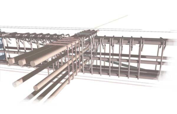
Reinforcement details:

Reference books
- Limit state design of reinforced concrete by B.C. Punmia, Ashok kumar jain, Arun kumar jain
- IS CODE 456-2000


Cross beams details
Cross beams are horizontal structural members used to stiffen buildings against lateral loads acting perpendicular to their axis. They span horizontally to transfer lateral wind and seismic forces between vertical structural elements like shear walls or frames.
While normal beams develop vertical shear forces and bending moments, the shear and moments in cross beams occur in a horizontal transverse direction due to lateral loading.
Cross beam reinforcement layouts differ from conventional beams, often with more confinement stirrups for ductility and top/bottom rebar to handle tension/compression stresses induced by horizontal bending.
They are usually designed and detailed to provide ductility, enabling large deflections during events like earthquakes while limiting structural damage.
I will post a new article giving a detailed information about this topic.