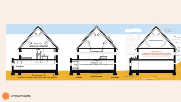
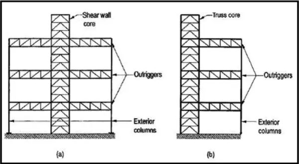
Structural cross beams are vital horizontal members designed to resist lateral wind and seismic forces impacting buildings.
Properly integrating cross beams stiffens the structure, limiting hazardous wrecking and damage to vertical framing elements during intense environmental loading conditions.
While conventional floor and roof beams support vertical gravity loads between columns, uniquely purposed cross beams span transversely between shear walls and lateral force resisting frames.
This ties the building together along its width and depth plane to resist dangerous lateral inter-story drift.
Though cross beam shapes and materials like steel or reinforced concrete resemble typical beams, their specialized reinforcements, analysis methods, and connection mechanisms suit the perpendicular shear and bending moment demands induced by earthquakes and storm winds.
By understanding cross beam earthquake-resistant design codes and best detailing practices for achieving ductility, structural engineers can optimize building stability and ruggedness..
What is a Cross Beam?
Cross beams are placed as “ties” between shear walls, braced frames, or other vertical building elements to resist horizontal seismic and wind forces.
Designed to limit building racking, cross beams stiffen structures against transverse external loads. Though made of steel, timber, or reinforced concrete like standard beams, reinforcement and connections suit their lateral load paths.

Purpose of Cross Beams
Cross beams brace the structural core, providing enhanced shear rigidity and ductility.
Properly integrating cross beams distributes environmental lateral loads evenly to shear walls per governing design codes like ASCE 7-16 minimum requirements. This prevents structural damage or instability during seismic events.
Classification of Cross Beams
Simple span cross beams connect directly between columns or walls in single bay openings at one level only.
Continuous cross beams have multiple spans over several bays for longer, staggered openings.
Some are designed as moment frames if joining columns spaced further apart to resist lateral drift through ductile bending.
Difference between cross beam and conventional Beam
- Loading Direction – Beams resist gravity loads vertically, cross beams resist lateral wind/seismic loads horizontally.
- Force Application – Vertical loads induce shear & bending in beams along their axis. Lateral loads induce perpendicular shears & moments in cross beams.
- Spans – Beams often have longer clear spans than cross beam lengths between walls.
- Critical Stresses – Tension/compression bending in beams. Shear stress and transverse bending prevalent in cross beams.
- Joints – Beam connections typically vertical shear joints. Cross beams have lateral force transfer joints.
- Ductility – Cross beams designed for higher ductility to withstand seismic racking deformations.
- Reinforcing – More robust confinement stirrups and anchorage used in ductile cross beam detailing.
- Analysis – Beams analyze vertical loading. Advanced analysis confirms cross beam impact on inter-story drift.
- Codes – Beam design per (IS 456:2000) bending codes. Seismic codes govern cross beam ductility and detailing.(ACI, ASCE and IBC) codes
- Cost – Simple beam forms are more economical than intricately reinforced cross beams.
The differences in orientation, stress function, and building dynamics lead to distinctly different design, analysis and detailing methods between structural beams and cross beams in construction.
codes for design of reinforced concrete cross beam
The main codes and standards used in the design and detailing of cross beams are:
ASCE 7-16 – Minimum Design Loads and Associated Criteria for Buildings and Other Structures
- Provides requirements for calculating wind, earthquake, snow and other lateral environmental loads used to determine design forces on cross beams.
ACI 318 – Building Code Requirements for Structural Concrete
- Outlines detailed requirements and guidelines for reinforced concrete cross beam analysis, ductile detailing, dimensioning and construction to withstand seismic demands.
AISC 360 – Specification for Structural Steel Buildings
- Contains regulations for determination of seismic design requirements, analysis methods and detailing of structural steel cross beams and connections.
AWC SDPWS – Special Design Provisions for Wind and Seismic
- Used specifically for timber and engineered wood cross beams lateral force resisting systems under wind or seismic loading.
IBC 2018 – International Building Code
- General building code which sets the governing criteria for lateral force-resisting systems involving cross beams, such as allowable drift limits.
Adhering to code requirements ensures cross beams meet minimum lateral strength and ductility performance criteria, preventing structural failure during intense environmental loading events.
Reinforced Concrete Cross Beam Design Standards
ACI Code 318 dictates reinforced concrete cross beam design and ductile detailing requirements including:
- Minimum cross beam widths and depths are set for adequate shear strength. Minimum width of 12 inches, and depth related to span lengths.
- Longitudinal reinforcement bars should be anchored using bend hooks or straight bar development lengths beyond joints.
- Stirrups and ties must meet minimum shear reinforcement spacing and volumetric ratios. Three stirrups uniformly spaced at maximum of d/2 or 12 inches.
- Transverse ties and spirals required as confinement reinforcement at beam-column joints where ductility is needed when moments reverse.
- Lap splice lengths of rebar dictated based on bar diameter and concrete compressive strength to ensure sufficient continuity.
- Special transverse reinforcement provided at any dapped or notched zones of reduced cross beam depth.
Covering standards ensures proper cross beam detailing and construction for ductile response meeting code prescribed lateral deformations.
Design of RCC Cross Beams and Reinforcement Details
Determine Design Loads
- Analyze dead, live, wind, seismic and other lateral loads per ASCE 7-16 based on building location and occupancy
Establish Structural System and Layout
- Locate cross beam spans, connections within overall seismic force-resisting system meeting IBC guidelines
Select Trial Cross Beam Size
- Estimate initial depth and width dimensions based on spans following ACI 318 minimums
Conduct Structural Analysis
- Model cross beam-to-column joints and wall connections analyzing effects on structure per IBC drift limits
Check Member Strengths
- Calculate beam shears, stresses and reinforcing needs in accordance with ACI 318 provisions
Detail Reinforcement and Connections
- Detail continuity and anchorage per ACI 318 ductility and splice length provisions
Evaluate Serviceability
- Limit drift and deformations to IBC requirements
Finalize Construction Drawings
- Fully detail for construction planning and inspection per ACI 318
The relevant building code requirements drive each phase of the cross beam design methodology focused on ductile seismic performance.
example of cross beam design
Here is an example reinforced concrete cross beam design with detailed calculations per code in kN/m units, including reinforcement detailing:
Design Data:
- Clear span (L) = 6 m
- Loads:
- Dead (D) = 22 kN/m
- Live (L) = 12 kN/m
- Seismic (E) = 0.4W=14 kN/m (calculated)
- Factored load (w) = 1.2D + 1.0L + 1.0E = 56 kN/m
- f’c = 30 MPa
- fy = 400 MPa
Shear Design:
Vu = wL/2 = 56 kN/m x 6 m / 2 = 168 kN
φVc = φ(0.53√f’c)bw d = 350 kN > Vu, OK (ACI 318-19 Eqn 11.1)
Moment Design:
Mu = wL2/8 = 56 kN/m x (6 m)2 / 8 = 252 kN-m
As, req = Mu/φfy(d-a/2) = 860 mm2
Use 3-25mm dia bars top and bottom
d = 500 mm, a = 65 mm (CSA A23.3-19 Cl 10.5, 10.7)
Deflection Check DL + LL deflection < (span/240)
Δallow = Span/240 = 6 m / 240 = 25 mm
Δcalc = 22 mm < Δallow, OK (IBC 2018 Table 1604.3)
Rebar Detailing:
- 3-25mm top bars, 3-25mm bottom bars
- 10M stirrups @ 300 mm c/c, 65mm cover
Satisfies code requirements for a 6m RC cross beam design with reinforcement details, using SI metric units.
Reinforcement Detailing:
Longitudinal Bars:
- 3-25 mm diameter bars top layer
- 3-25 mm diameter bars bottom layer
Anchorage Lengths (CSA A23.3-19 – Cl 12.2.2):
- Straight Bars: ld = 550 mm
- 90° Hooks: ld = 550 mm
Splice Length (CSA A23.3-19 – Cl 12.15.5)
- Class B (f’c = 30 MPa), ld = 1,375 mm
Stirrups/Ties:
- 10M @ 300 mm c/c
- 135° hooks, bend diameter = 300 mm
- Clear cover = 65 mm
This detailing meets anchorage, lap splice and ductile stirrup requirements per CSA 23.3-19 code for the seismic design of the 6m reinforced concrete cross beam.


