RCC stands for reinforced cement concrete, which means that concrete is reinforced with steel bars to increase its strength and durability. Concrete is strong in compression while a minimum longitudinal reinforcement is provided in the column to assist tensile stress.
Column is an important component of RC structure. It may be defined as a member carrying axial load which causes compressive stress.
Reinforced concrete columns are critical structural elements that transfer loads from beams, slabs, and other components to the foundation. Their design of RCC column must adhere to building codes to ensure safety and structural integrity.
The column should be designed to resist both axial and lateral forces, and to prevent buckling or crushing failure. The column should also have adequate reinforcement and cover to protect it from corrosion and fire.
According to IS 456, the column design process involves determining the rcc column details such as cross-sectional dimensions, reinforcement details of column, and longitudinal bars in column.
The design of RCC columns is governed by various codes and standards, such as IS 456:2000 in India, ACI 318-19 in the USA, and BS 8110 in the UK. These codes provide guidelines and formulas for calculating the cross-sectional area, reinforcement ratio, minimum eccentricity, and other parameters of the column.
Overview of RCC Column Design
The codes also specify the minimum and maximum limits for these parameters to ensure safety and economy.
Steps in RCC Column Design
- The size and shape of the column are determined based on the structural requirement of the project.
- Taking into consideration the self weight of the column, the axial load and the bending moment acting on the column are calculated.
- Grade of the concrete and the steel to be used is chosen. The grade of concrete is usually specified by its compressive strength, while the grade of steel is specified by its yield strength.
- Assume a suitable percentage of reinforcement for the column. The reinforcement ratio is the ratio of the area of steel to the area of concrete in the cross-section of the column.
- Minimum reinforcement is required to prevent the brittle failure of column and maximum to avoid congestion and ensure proper bond between steel and concrete.Check the minimum and maximum reinforcement limits as per the relevant code of practice.
- calculate the longitudinal reinforcement bars for the column. The longitudinal bars are placed along the length of the column to provide resistance to axial compression and bending. The number, diameter, and spacing of the bars are determined based on the reinforcement ratio, the bending moment, and the code provisions.
- calculate the transverse reinforcement for the column. The transverse reinforcement consists of ties or stirrups that are placed around the longitudinal bars at regular intervals. The transverse reinforcement provides confinement to the concrete core, enhances its ductility, and resists shear forces. The diameter, spacing, and shape of the ties or stirrups are determined based on the shear force, the column size, and the code provisions.
- Draw the detailed reinforcement diagram for the column showing the size, location, and spacing of all the bars.
Design of a RCC column as per ACI 318-19 with an example
- Determine loads on column (Dead, Live, Wind, Seismic etc.)
For example, Axial Load = 300 kN
Moments
Mx = 10 kN.m
My = 8 kN.m - Select trial column dimensions
Say 400mm x 600mm - Find capacity reduction factors
φ for flexure = 0.9
φ for axial compression = 0.65 - Determine material strengths
f’c = 25 MPa , fy = 415 MPa - Calculate effective length factor K
Assuming Kx = Ky = 1 - Determine cross sectional properties
Gross Area, A = 400 * 600 = 240,000 mm2
Moment of Inertia about x-axis, Ix = 1,440,000 cm4
Moment of Inertia about y-axis, Iy = 2,160,000 cm4 - Calculate factored axial load and moments
Pu = (1.2) (300) / 0.65 = 554 kN
Mux = 1.25 * 10 = 12.5 kN.m
Muy = 1.25 * 8 = 10 kN.m - Determine Pn-max & Mn-max values from ACI interaction diagrams
- Check combined loading as per ACI Pu/φPn + Mnux/φMnx ≤ 1.0 AND
Pu/φPn + Mnuy/φMny ≤ 1.0 (OK in our case) - Check deflection (delta allowable), shear strength and anchorage requirements.
That completes basic design check for the RCC column.
General Reinforcement Steps in RCC column Design
- Minimum number of bars for the rectangular column is 4 and circular column is 6.
- The grate of concrete to be used M20.

4 Bars in Rectangular and 6 bars in circular
- Percentage of steel in the RCC column is taken as 0.8% to 6% of the gross area.
- Longitudinal steel rod or main main steel rod diameter should not be less than 12mm and not greater than 50mm.
- Steel rod should be straight while overlapping.
- Minimum diameter of ties should not be less than 1/4th of the main rod dia or less than 5mm.
- The minimum clear cover of concrete outside of the longitudinal bar should not be less than 40mm.
- Width of the column should be B/D ≥ 0.4 and B ≥ 400.
Basic Steps used in column design
- The minimum eccentricity values as per IS 456 code provision is calculated by using below formula in the column design
We need to consider a minimum or greater than 20 mm value as eccentricity value.
emin = (L/500) + (D/30) ≥ 20 mm
For non rectangular columns minimum eccentricity is taken as
emin = Le/300 or 20mm (whichever is less)
2. The calculation of main steel is determined by using the below formulae which is shown below

3. The gross area, steel area required for the column section is determined by using below formulae
Ag=Asc + Ac
Ag = gross area of steel,
Asc = area of longitudinal reinforcement
Ac = area of core,
Le = effective length of column
Pu = total axial load,
Design of RCC column as per IS 456 code – Example
Design reinforcement in a circular column of diameter 300mm with helical reinforcement to support a factored load of 1500 KN . The column has an unsupported length 3m and is braced against sideways. Take M-20 grade concrete, Fe 415 HYSD bars.
Given data
- Diameter of column = 300mm
- Length of column Le = 3000mm
- Factored load Pu = 1500 KN
- fck = 20 N/mm2
- fy = 415 N/mm2
- Slenderness ratio
- Le /D = 3000/300 = 10 < 12
Hence the column is designed for short column.
- Minimum eccentricity
emin = [ L/500 + D/30] = [ 3000/500 + 300/30]
= 16mm( take 20mm)
- Longitudinal reinforcement

(1500 X 10^3)/ 1.05 = [ (0.4 X 20 X πX 300 X 300) + ( 0.67 X 415) -(0.4 X 20) Asc]
Solving we get
Asc = 3197 mm^2
Asc min = 0.8% of gross sectional area = ( 0.8 Xπ/4X 300 X 300) = 565mm^2
Therefore if we provide 6 bars of 28mm diameter i.e Asc = 3969 mm^2
- Helical reinforcement(spirals)
Assuming a clear cover of 40mm over the spirals
Core diameter = 300- (2 X 40) = 220mm
Area of core = Ac = (π X 220 X 220 /4) – 3696 = 34317mm^2
Volume of core Vc = 3431X1000 mm^3
GROSS AREA OF CROSS SECTION = Ag = π/4 X 300 X 300 = 70685 mm^2
Using 8mm dia helical spirals at pitch p,
volume per metre length = Vns = π(300-80-8)50 X(1000/p)mm^3/m

Solving the above we get p= 52.78mm
Codal restriction for pitch from clause 39.4.9(IS 456)
P>25mm or (3 times dia of helix) = 3 X 8 = 24 mm
p<75mm or (core diameter/6) = 220/6 = 36.6mm
So provide 8mm spirals at a pitch of 36 mm
FAQ
What is column and strut?
The basic difference between the column and strut is the column is avertical member designed to take axial compressive loads, while strut is a horizontal or vertical or inclined member that is designed to take axial loads.
What is a pedestal in RCC?
In rcc pedestal is defined as a compressive member whose effective length does not exceed its lateral dimension. Its minimum height is 45cm.
Reinforcement details
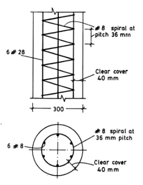
The reinforcement details of circular helical column is as shown in the figure
8mm spirals at a pitch of 36 mm
6 bars of 28mm diameter
Clear cover = 40mm


Source: reinforced concrete design IS 456-2000, by N KRISHNA RAJU , R.N PRANESH
In civil column design, engineers follow a systematic approach to determine the column’s dimensions, reinforcement details, and detailing requirements. They may use design aids, software, or circular column design example problems to streamline the process. Understanding the reinforcement details of column and adhering to code provisions is crucial for designing safe and efficient rcc column structures.


